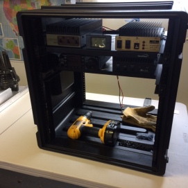
Its been awhile since I updated the blog. The Rover Rebuild is for the most part complete and works very well. For the June 2017 VHF Contest I barely put together a stati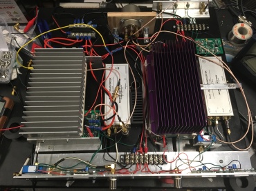 on for 50-1296 MHz, and the 2304 & 3456 MHz rack was the next build. The 2304 amplifier shown on the left was built from a “PyroJoe” 30W board from Ebay and a chunk of heatsink. The purple 3456 amplifier on the right was another Ebay purchase, this time a fully contained fully operational amplifier originally made for WiMAX. This amplifier has forward and reverse power detectors which is great since I don’t have a SWR meter for this band. If you saw the 902 & 1296 Rack pictures, you will see that I was not so careful this time routing wires and making things look neat.
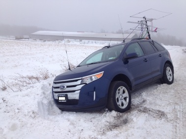
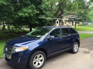
This picture shows the antenna setup for the 222+ (August) distance contest. The 3.5G WiMAX parabolic antenna sits in the center of the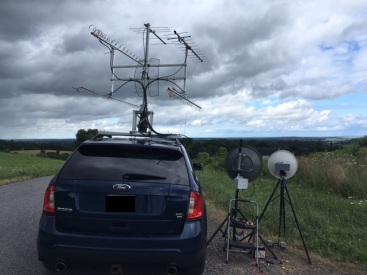 setup with loopers on 902, 1296, and 2304. A small 5-element yagi on 222 and 11-element 432 yagi round out the bottom 6 bands for this event. The 5G and 10G setups are tripod mounted to the right of the vehicle. Since 5G and 10G contacts are somewhat rare, I had the luxury of sitting on my butt and simply use the rotor to point antennas. For several years I have manually pointed antennas. This method works ok on 6m and 2m, but becomes a real pain above 432 MHz. Having used the roof rack rotor in four contests now, I can definitely see how much easier it is to move through the bands. The entire roof rack system can be safely lifted and placed by one person by using the roof rack as a pivot point and placing a wooden 2×4 in the middle of the roof to prevent “additional” roof damage during installation. Perhaps someday I will add a rotor system for the hitch mounted 6m/2m antennas.
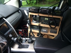
The pictures below show an example of how much neater the new rover setup looks compared to past setups. The two cables in the back of the console are for PTT switching and IF relay switching going to the rack in the rear of the vehicle. Additional connections are required for power, key extension, speaker connection, and FM antennas. The deep cycle batteries now sit in the rear of the vehicle and an inverter sits on the passengers floor area for powering the laptop and rotor controller.


The rack system has proved very useful and efficient. Its a little heavy (but possible) for one person, but quite easy to load in the vehicle with the help of my wife. The view from the rear shows the rack with the nearly bare 2304/3456 shelf, but provides a decent look at the power system. The 6V golf cart batteries are charged by the vehicle power system and the voltage booster keeps electronics happy at 13.4 – 13.8V at all times.


The system has been a pleasure to build and operate. I was finally able to reach the 100 multiplier goal I had set for myself in the September 2017 VHF contest and really enjoyed myself staying busy the whole contest. I hope that my blog posts motivate just one person to head into the garage and experience the Joy of Building !


VHF/UHF/Microwave contesting is all about experimenting, building, learning, and growing in a competitive environment. WINNING should be the consequence and not the goal. If you compete against yourself and use others ideas as inspiration, you will always stay motivated.
 The rack is a 19″ 12U molded plastic unit with rails in the front and the back. There is about 17.5″ between the front and back rails. In the picture I have set the 144, 222, and 432 amplifiers on some shelves along with the IC-7000 and a battery monitor. I dont expect the layout to look like this when done, but it gives an idea of what I am trying to do with it. The lower two shelves will contain the microwave equipment. One shelf will be 902 & 1296 while the other will contain 2304 & 3456. Somewhere in here I will need to fit the IF relay, a fuse block, and the 222 transverter.


 nts. Those delivered so far are shown in the picture above. I have the Kuhne Electronic 200 mW transverter, a 2W power amplifier, and a coax switch. I have acquired an FT-817 QRP HF-70cm radio and an open frame backpack. The biggest challenge so far has been a lighweight antenna. The Procom 48cm model seems perfect weighing in at under 3 pounds, but it has been difficult to purchase. A company in Germany seems willing to ship to the US, so I will see how it works out. In the meantime I have a NEMA 4 rated aluminum enclosure on backorder. It has a similar foot print to the cardboard box, but will be a bit taller. The empty space will be reserved for a future 10 MHZ GPS disciplined oscillator. I quickly went overbudget with the addition of the FT-817, so the oscillator will have to wait.